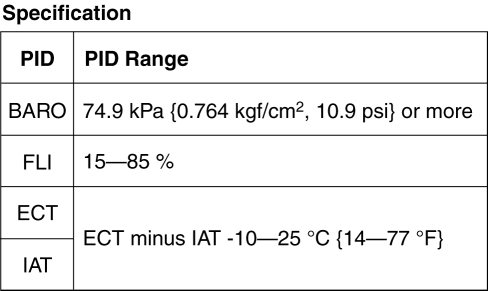
< Previous   Next >

2014 - Mazda6 - Engine

ENGINE CONTROL SYSTEM OPERATION INSPECTION [SKYACTIV-G 2.5]

Main Relay Operation Inspection

1. Verify that the main relay clicks when the ignition is switched ON and then off.

Intake Manifold Vacuum Inspection

1. Verify the air intake hoses are installed properly.
2. Start the engine and let it idle.
3. Disconnect the vacuum hose between the intake manifold and purge solenoid valve from the intake manifold side.
4. Connect a vacuum gauge to the intake manifold and measure the intake manifold vacuum.

NOTE:

Electric Variable Valve Timing Driver Control System Inspection

1. Connect the M-MDS to the DLC-2.
2. Perform the KOER self test. (See KOEO/KOER SELF TEST [SKYACTIV-G 2.5].)
3. Verify that DTC P0010:00 or P1380:00 is not displayed. (See ON-BOARD DIAGNOSTIC TEST [SKYACTIV-G 2.5].)
4. Perform the Drive Mode 03 (Variable Valve Timing, A/F Sensor Heater, HO2S Heater, A/F Sensor, HO2S and TWC Repair Verification Drive Mode). (See OBD-II DRIVE MODE [SKYACTIV-G 2.5].)
5. Verify that DTC P0011:00 or P0012:00 is not displayed. (See ON-BOARD DIAGNOSTIC TEST [SKYACTIV-G 2.5].)
6. Access the following PCM PIDs using the M-MDS. (See ON-BOARD DIAGNOSTIC TEST [SKYACTIV-G 2.5].)

CAUTION:

7. Accelerate and decelerate the vehicle, and drive at normal speed, and verify that the data monitor item VT IN_ACT value changes in conjunction with the VT IN_DES value.
Related PIDs

Item (definition)

Unit/Condition

Definition

Condition/Specification (Reference)

VT IN_ACT

°

Actual intake valve timing

  • Displays actual intake valve timing

VT IN_DES

°

Desired intake valve timing

  • Displays desired intake valve timing


Engine Oil Solenoid Valve Control System Inspection

1. Connect the M-MDS to the DLC-2.
2. Perform the KOER self test. (See KOEO/KOER SELF TEST [SKYACTIV-G 2.5].)
3. Verify that DTC P06DA:00 is not displayed. (See ON-BOARD DIAGNOSTIC TEST [SKYACTIV-G 2.5].)
4. Inspect the engine oil pressure. (See OIL PRESSURE INSPECTION [SKYACTIV-G 2.5].)
5. Access the following PCM PIDs using the M-MDS. (See ON-BOARD DIAGNOSTIC TEST [SKYACTIV-G 2.5].)
6. With the engine coolant temperature at 98 °C {208 °F}, increase the engine speed to 4,000 rpm or higher, and verify that the oil pressure gauge value changes when the data monitor item OIL_P_SOL value is changed from ON to OFF.
Related PIDs

Item (definition)

Unit/Condition

Definition

Condition/Specification (Reference)

ECT

°C, °F

Engine coolant temperature (No.1)

  • Displays ECT

V

  • ECT is 20 °C {68 °F}: Approx. 3.10 V

  • ECT is 40 °C {104 °F}: Approx. 2.16 V

  • ECT is 60 °C {140 °F}: Approx. 1.40 V

  • ECT is 80 °C {176 °F}: Approx. 0.87 V

  • ECT is 100 °C {212 °F}: Approx. 0.54 V

OIL_P_SOL

Off/On

Engine oil solenoid valve

  • ECT below 98 °C {208 °F} and engine speed below 4,000 rpm: On

  • ECT above 98 °C {208 °F} or engine speed above 4,000 rpm: Off

RPM

RPM

Engine speed

  • Displays engine speed


Drive-by-wire Control System Inspection

Engine coolant temperature compensation inspection
1. Connect the M-MDS to the DLC-2.
2. Select the following PIDs: (See ON-BOARD DIAGNOSTIC TEST [SKYACTIV-G 2.5].)
3. Verify that the engine is cold, then start the engine.
4. Verify that the engine speed decreases as the engine warms up.
Related PIDs

Item (definition)

Unit/Condition

Definition

Condition/Specification (Reference)

ECT

°C, °F

Engine coolant temperature (No.1)

  • Displays ECT

V

  • ECT is 20 °C {68 °F}: Approx. 3.10 V

  • ECT is 40 °C {104 °F}: Approx. 2.16 V

  • ECT is 60 °C {140 °F}: Approx. 1.40 V

  • ECT is 80 °C {176 °F}: Approx. 0.87 V

  • ECT is 100 °C {212 °F}: Approx. 0.54 V

IAT

°C, °F

Intake air temperature (No.1)

  • Displays IAT (No.1)

V

  • IAT is 20 °C {68 °F}: Approx. 2.70 V

  • IAT is 40 °C {104 °F}: Approx. 1.80 V

  • IAT is 60 °C {140 °F}: Approx. 1.20 V

RPM

RPM

Engine speed

  • Displays engine speed


Load compensation inspection
1. Start the engine and let it idle.
2. Connect the M-MDS to the DLC-2.
3. Verify that DTC P0506:00 or P0507:00 is not displayed. (See ON-BOARD DIAGNOSTIC TEST [SKYACTIV-G 2.5].)
4. Select the RPM PID.

NOTE:

5. Verify that the engine speed is within specification under each load condition.
Related PIDs

Item (definition)

Unit/Condition

Definition

Condition/Specification (Reference)

RPM

RPM

Engine speed

  • Displays engine speed


Electronic Control Throttle Operation Inspection
1. Connect the M-MDS to the DLC-2.
2. Perform the KOEO or KOER self test. (See KOEO/KOER SELF TEST [SKYACTIV-G 2.5].)
3. Verify that none of the following DTCs are displayed:
4. Access the following PCM PIDs using the M-MDS. (See ON-BOARD DIAGNOSTIC TEST [SKYACTIV-G 2.5].)
5. With the accelerator pedal not depressed and with it depressed to the floor, verify that the data monitor item ETC_ACT value changes in conjunction with the ETC_DSD value.
Related PIDs

Item (definition)

Unit/Condition

Definition

Condition/Specification (Reference)

ETC_ACT

°

Throttle control

    Switch ignition ON (engine off)
  • Accelerator pedal released: Approx. 12.89 °

  • Accelerator pedal depressed: Approx. 86.03 °

    Idle (after warm up)
  • Accelerator pedal released: Approx. 3.2 °

ETC_DSD

%

Throttle control desired

  • Displays target TP angle (percent)

°

  • Displays target TP angle


Brake override system operation inspection

NOTE:

1. Start the engine and let it idle.
2. Verify that the engine speed becomes less than 1,200 rpm under the following conditions.

Fuel Injector Operation Inspection

If simulation function of M-MDS is used:

STEP

INSPECTION

ACTION

1

Start the engine and warm it up completely.

Access the INJ_1, INJ_2, INJ_3 and INJ_4 PIDs using the M-MDS.

(See ON-BOARD DIAGNOSTIC TEST [SKYACTIV-G 2.5].)

Turn each fuel injector from on to off using the PIDs for each cylinder.

Does the engine speed drop?

Yes

Fuel injectors work properly.

No

Engine speed does not drop an any cylinder:

  • Go to the next step.

Engine speed drops on some cylinders:

  • Go to Step 4.

2

Perform the Main Relay Operation Inspection.

(SeeMain Relay Operation Inspection.)

Does the main relay work properly?

Yes

Go to the next step.

No

Repair or replace the malfunctioning part according to the inspection results.

3

Inspect the fuel injector of the suspected cylinder.

(See FUEL INJECTOR INSPECTION [SKYACTIV-G 2.5].)

Is there any malfunction?

Yes

Replace the fuel injector.

(See FUEL INJECTOR REMOVAL/INSTALLATION [SKYACTIV-G 2.5].)

No

Inspect the fuel injector power and/or ground systems related wiring harness and connectors for the suspected cylinder.

4

Perform the KOER self test using the M-MDS.

(See KOEO/KOER SELF TEST [SKYACTIV-G 2.5].)

Are the DTCs P0201:00, P0202:00, P0203:00 and/or P0204:00 present?

Yes

Go to the appropriate DTC inspection.

(See DTC P0201:00 [SKYACTIV-G 2.5].)

(See DTC P0202:00 [SKYACTIV-G 2.5].)

(See DTC P0203:00 [SKYACTIV-G 2.5].)

(See DTC P0204:00 [SKYACTIV-G 2.5].)

No

Go to the next step.

5

Inspect the fuel injector of the suspected cylinder.

(See FUEL INJECTOR INSPECTION [SKYACTIV-G 2.5].)

Is there any malfunction?

Yes

Replace the fuel injector.

(See FUEL INJECTOR REMOVAL/INSTALLATION [SKYACTIV-G 2.5].)

No

Inspect the following for the suspected cylinder:

  • PCM terminals (pulled-out pins, corrosion)

  • Fuel injector terminals (pulled-out pins, corrosion)


If simulation function of M-MDS is not used:

STEP

INSPECTION

ACTION

1

Perform the KOER self test using the M-MDS.

(See KOEO/KOER SELF TEST [SKYACTIV-G 2.5].)

Are the DTCs P0201:00, P0202:00, P0203:00 and/or P0204:00 present?

Yes

Go to the appropriate DTC inspection.

(See DTC P0201:00 [SKYACTIV-G 2.5].)

(See DTC P0202:00 [SKYACTIV-G 2.5].)

(See DTC P0203:00 [SKYACTIV-G 2.5].)

(See DTC P0204:00 [SKYACTIV-G 2.5].)

No

Go to the next step.

2

Inspect the fuel injector of the suspected cylinder.

(See FUEL INJECTOR INSPECTION [SKYACTIV-G 2.5].)

Is there any malfunction?

Yes

Replace the fuel injector.

(See FUEL INJECTOR REMOVAL/INSTALLATION [SKYACTIV-G 2.5].)

No

Go to the next step.

3

Inspect the following for the suspected cylinder:

  • Fuel injector power and/or ground system related wiring harnesses and connectors

  • PCM terminals (pulled-out pins, corrosion)

  • Fuel injector terminals (pulled-out pins, corrosion)

Is there any malfunction?

Yes

Repair or replace the malfunctioning part according to the inspection results.

No

Replace the PCM.

(See PCM REMOVAL/INSTALLATION [SKYACTIV-G 2.5].)


Fuel Cut Control System Inspection

NOTE:

If data monitor function of M-MDS is used:
1. Warm up the engine and idle it.
2. Connect the M-MDS to the DLC-2.
3. Select the RPM and the FUELPW PIDs. (See ON-BOARD DIAGNOSTIC TEST [SKYACTIV-G 2.5].)
4. Monitor both PIDs while performing the following steps:
a. Depress the accelerator pedal and increase the RPM PID to 4,000 rpm.
b. Quickly release the accelerator pedal (brake pedal is not depressed) and verify that the FUELPW PID is 0 msec, and 2—5 msec when the RPM PID drops below 1,200 rpm.
Related PIDs

Item (definition)

Unit/Condition

Definition

Condition/Specification (Reference)

FUELPW

Sec

Fuel injector duration

  • Idle (after warm up): Approx. 1.4 ms

  • Racing (engine speed is 2,000 rpm): Approx. 1.1 ms

  • Racing (engine speed is 4,000 rpm): Approx. 1.0 ms

RPM

RPM

Engine speed

  • Displays engine speed


If data monitor function of M-MDS is not used:
1. Warm up the engine and idle it.
2. Measure the fuel injector control signal wave profile using the oscilloscope while performing the following steps:
a. Depress the accelerator pedal and increase the engine speed to 4,000 rpm.
b. Quickly release the accelerator pedal (brake pedal is not depressed) and verify that the wave profile constant B+, and the wave appears when the engine speed drops below 1,200 rpm. (See PCM INSPECTION [SKYACTIV-G 2.5].)

Fuel Pump (Low-pressure Side) Operation Inspection

1. Connect the M-MDS to the DLC-2.
2. Remove the fuel-filler cap.
3. Switch the ignition ON (engine off).
4. Turn the fuel pump relay from off to on using the FP PID and inspect if the operation sound of the fuel pump is heard. (See ON-BOARD DIAGNOSTIC TEST [SKYACTIV-G 2.5].)
5. Measure the voltage at the wiring harness side fuel pump unit terminal A with the FP PID turned on.

Fuel Pump (Low-pressure Side) Control System Inspection

If simulation function of M-MDS is used:
1. Connect the M-MDS to the DLC-2.
2. Switch the ignition ON (engine off).
3. Select the FP PID. (See ON-BOARD DIAGNOSTIC TEST [SKYACTIV-G 2.5].)
4. Turn the fuel pump relay from off to on and inspect if the operation sound of the fuel pump relay is heard.
If simulation function of M-MDS is not used:
1. Crank the engine and verify that the fuel pump relay operation sound is heard.
2. If the operation sound is not heard, inspect the following:

Spark Test

1. Disconnect the fuel pump relay and fuel injector relay.
2. Verify that each ignition coil and connector is connected properly.
3. Inspect the ignition system in the following procedure:

WARNING:


STEP

INSPECTION

ACTION

1

Disconnect the ignition coils from the spark plugs.

Remove the spark plugs.

(See SPARK PLUG REMOVAL/INSTALLATION [SKYACTIV-G 2.5].)

Verify that the spark plugs do not have carbon deposits.

Is there any malfunction?

Yes

Perform no-load racing at 4,000 rpm for 2 min, 2 times to burn off the carbon deposits.

Repeat this step.

No

Go to the next step.

2

Inspect the spark plugs for damage, wear, and proper plug gap.

Is there any malfunction?

Yes

Re-gap or replace the spark plugs, then go to the next step.

(See SPARK PLUG REMOVAL/INSTALLATION [SKYACTIV-G 2.5].)

No

Go to the next step.

3

Reconnect the spark plugs to the ignition coil.

Ground the spark plugs to the engine.

Is a strong blue spark visible at each cylinder while cranking the engine?

Yes

Ignition system is normal.

No

Some cylinders do not spark:

  • Go to the next step.

All cylinders do not spark:

  • Go to Step 5.

4

Switch the ignition off.

Inspect the wiring harness between the following terminals (wiring harness-side) for an open or short circuit:

  • Ignition coil/ion sensor No.1 terminal B—PCM terminal 1AY

  • Ignition coil/ion sensor No.2 terminal B—PCM terminal 1AT

  • Ignition coil/ion sensor No.3 terminal B—PCM terminal 1AO

  • Ignition coil/ion sensor No.4 terminal B—PCM terminal 1AJ

Is there any malfunction?

Yes

Refer to the wiring diagram and verify whether or not there is a common connector between the following terminals:

  • Ignition coil/ion sensor No.1 terminal B—PCM terminal 1AY

  • Ignition coil/ion sensor No.2 terminal B—PCM terminal 1AT

  • Ignition coil/ion sensor No.3 terminal B—PCM terminal 1AO

  • Ignition coil/ion sensor No.4 terminal B—PCM terminal 1AJ

    If there is a common connector:
  • Determine the malfunctioning part by inspecting the common connector and the terminal for corrosion, damage, or pin disconnection, and the common wiring harness for an open or short circuit.

  • Repair or replace the malfunctioning part.

    If there is no common connector:
  • Repair or replace the wiring harness which has an open or short circuit.

No

Inspect the ignition coil.

(See IGNITION COIL INSPECTION [SKYACTIV-G 2.5].)

Replace the ignition coil/ion sensor.

(See IGNITION COIL/ION SENSOR REMOVAL/INSTALLATION [SKYACTIV-G 2.5].)

5

Switch the ignition off.

Disconnect the ignition coil/ion sensor connectors.

Switch the ignition ON (engine off).

Measure the voltage at each ignition coil/ion sensor terminal A (wiring harness-side).

Is the voltage B+?

Yes

Go to the next step.

No

Inspect for power supply circuit in wiring harness between ignition switch and ignition coils.

Refer to the wiring diagram and verify whether or not there is a common connector between the following terminals:

  • Main relay terminal C—Ignition coil/ion sensor No.1 terminal A

  • Main relay terminal C—Ignition coil/ion sensor No.2 terminal A

  • Main relay terminal C—Ignition coil/ion sensor No.3 terminal A

  • Main relay terminal C—Ignition coil/ion sensor No.4 terminal A

    If there is a common connector:
  • Determine the malfunctioning part by inspecting the common connector and the terminal for corrosion, damage, or pin disconnection, and the common wiring harness for a short to power supply.

  • Repair or replace the malfunctioning part.

    If there is no common connector:
  • Repair or replace the wiring harness which has a short to power supply.

6

Switch the ignition off.

Inspect for continuity between terminal D (wiring harness-side) in each ignition coils and body ground.

Is there continuity?

Yes

Go to the next step.

No

Refer to the wiring diagram and verify whether or not there is a common connector between the following terminals:

  • Ignition coil/ion sensor No.1 terminal D—Body ground

  • Ignition coil/ion sensor No.2 terminal D—Body ground

  • Ignition coil/ion sensor No.3 terminal D—Body ground

  • Ignition coil/ion sensor No.4 terminal D—Body ground

    If there is a common connector:
  • Determine the malfunctioning part by inspecting the common connector and the terminal for corrosion, damage, or pin disconnection, and the common wiring harness for an open circuit.

  • Repair or replace the malfunctioning part.

    If there is no common connector:
  • Inspect for the following:

    • Open circuit between ignition coil/ion sensor No.1 and body ground

    • Open circuit between ignition coil/ion sensor No.2 and body ground

    • Open circuit between ignition coil/ion sensor No.3 and body ground

    • Open circuit between ignition coil/ion sensor No.4 and body ground

    • Loose or lifting ground point

      • Repair or replace the malfunctioning part.

Repeat from Step 1.

7

Inspect the connection of PCM and ignition coil/ion sensor connectors.

Are the PCM connector or ignition coil/ion sensor connectors poorly connected?

Yes

Repair or replace the connector.

Repeat from Step 1.

No

Go to the next step.

8

Inspect the CKP sensor and crankshaft pulley.

(See CRANKSHAFT POSITION (CKP) SENSOR INSPECTION [SKYACTIV-G 2.5].)

Is there any malfunction?

Yes

Repair or replace the malfunctioning part according to the inspection results.

(See CRANKSHAFT POSITION (CKP) SENSOR REMOVAL/INSTALLATION [SKYACTIV-G 2.5].)

No

Inspect for an open or short circuit in wiring harness and connector of the CKP sensor.

Repair or replace the malfunctioning part according to the inspection results.


Purge Control System Inspection

If simulation function of M-MDS is used:
1. Start the engine.
2. Disconnect the vacuum hose between the purge solenoid valve and the charcoal canister.
3. Put a finger to the purge solenoid valve and verify that there is no vacuum applied when the engine is cold.
4. Connect the M-MDS to the DLC-2 and verify that DTC P0443:00 is displayed. (See ON-BOARD DIAGNOSTIC TEST [SKYACTIV-G 2.5].)
5. Select the EVAPCP PID.
6. Increase the duty value of the purge solenoid valve to 50 % and inspect if the operation sound of the valve is heard.
7. Warm up the engine to normal operating temperature.
8. Monitor the EVAPCP PID using the M-MDS, and drive the vehicle approx. 2000 rpm for 30 s or more. (See ON-BOARD DIAGNOSTIC TEST [SKYACTIV-G 2.5].)
Related PIDs

Item (definition)

Unit/Condition

Definition

Condition/Specification (Reference)

APP1

%

APP sensor No.1

  • Accelerator pedal released: Approx. 15%

  • Accelerator pedal depressed: Approx. 82%

V

  • Accelerator pedal released: Approx. 0.75 V

  • Accelerator pedal depressed: Approx. 4.1 V

APP2

%

APP sensor No.2

  • Accelerator pedal released: Approx. 7.45%

  • Accelerator pedal depressed: Approx. 41%

V

  • Accelerator pedal released: Approx. 0.38 V

  • Accelerator pedal depressed: Approx. 2.05 V

EVAPCP

%

Purge solenoid valve duty value

  • Idle (after warm up): Approx. 0%

  • Racing (Engine speed 2,000 rpm): 4.3—35%

  • Racing (Engine speed 4,000 rpm): Approx. 66%

MAF

g/Sec

Mass air flow

  • Displays MAF

V

  • Switch ignition ON (engine off) (MAF: 0.59 g/s {0.078 lb/min}): Approx. 0.72 V

  • Idle (after warm up) (MAF: 2.17 g/s {0.287 lb/min}): Approx. 0.86 V

  • Racing (engine speed is 2,000 rpm) (MAF: 4.73 g/s {0.626 lb/min}): Approx. 1.07 V

LOAD

%

Engine load

  • Idle (after warm up): Approx. 17.64%

  • Racing (engine speed is 2,000 rpm): Approx. 14.51%

  • Racing (engine speed is 4,000 rpm): Approx. 21.17%

TP REL

%

Throttle position signal (relative value)

  • Accelerator pedal released: Approx. 12%

  • Accelerator pedal depressed: Approx. 82%


If simulation function of M-MDS is not used:
1. Start the engine.
2. Disconnect the vacuum hose between the purge solenoid valve and the charcoal canister.
3. Put a finger to the purge solenoid valve and verify that there is no vacuum applied when the engine is cold.
4. Warm up the engine to the normal operating temperature.
5. Stop the engine.
6. Connect the M-MDS to the DLC-2 and verify that DTC P0443:00 is displayed.
7. Switch the ignition ON (engine off).
8. Select the ECT PID. (See ON-BOARD DIAGNOSTIC TEST [SKYACTIV-G 2.5].)
9. Verify that the engine coolant temperature is above 60 °C {140 °F}.
10. Set the vehicle on a dynamometer or chassis roller.

WARNING:

11. Drive the vehicle at an engine speed to approx. 2000 rpm for 30 s or more.
12. Put a finger to the purge solenoid valve and verify that there is no vacuum applied during Step 2.
Related PIDs

Item (definition)

Unit/Condition

Definition

Condition/Specification (Reference)

APP1

%

APP sensor No.1

  • Accelerator pedal released: Approx. 15%

  • Accelerator pedal depressed: Approx. 82%

V

  • Accelerator pedal released: Approx. 0.75 V

  • Accelerator pedal depressed: Approx. 4.1 V

APP2

%

APP sensor No.2

  • Accelerator pedal released: Approx. 7.45%

  • Accelerator pedal depressed: Approx. 41%

V

  • Accelerator pedal released: Approx. 0.38 V

  • Accelerator pedal depressed: Approx. 2.05 V

ECT

°C, °F

Engine coolant temperature (No.1)

  • Displays ECT

V

  • ECT is 20 °C {68 °F}: Approx. 3.10 V

  • ECT is 40 °C {104 °F}: Approx. 2.16 V

  • ECT is 60 °C {140 °F}: Approx. 1.40 V

  • ECT is 80 °C {176 °F}: Approx. 0.87 V

  • ECT is 100 °C {212 °F}: Approx. 0.54 V

MAF

g/Sec

Mass air flow

  • Displays MAF

V

  • Switch ignition ON (engine off) (MAF: 0.59 g/s {0.078 lb/min}): Approx. 0.72 V

  • Idle (after warm up) (MAF: 2.17 g/s {0.287 lb/min}): Approx. 0.86 V

  • Racing (engine speed is 2,000 rpm) (MAF: 4.73 g/s {0.626 lb/min}): Approx. 1.07 V

LOAD

%

Engine load

  • Idle (after warm up): Approx. 17.64%

  • Racing (engine speed is 2,000 rpm): Approx. 14.51%

  • Racing (engine speed is 4,000 rpm): Approx. 21.17%

TP REL

%

Throttle position signal (relative value)

  • Accelerator pedal released: Approx. 12%

  • Accelerator pedal depressed: Approx. 82%


A/C Cut-off Control System Inspection

1. Start the engine.
2. Turn the A/C switch and fan switch on.
3. Verify that the A/C compressor magnetic clutch actuates.
4. Fully open the throttle valve and verify that the A/C compressor magnetic clutch does not actuate for 2—5 s.
Related PIDs

Item (definition)

Unit/Condition

Definition

Condition/Specification (Reference)

APP1

%

APP sensor No.1

  • Accelerator pedal released: Approx. 15%

  • Accelerator pedal depressed: Approx. 82%

V

  • Accelerator pedal released: Approx. 0.75 V

  • Accelerator pedal depressed: Approx. 4.1 V

APP2

%

APP sensor No.2

  • Accelerator pedal released: Approx. 7.45%

  • Accelerator pedal depressed: Approx. 41%

V

  • Accelerator pedal released: Approx. 0.38 V

  • Accelerator pedal depressed: Approx. 2.05 V


Cooling Fan Control System Inspection

1. Connect the M-MDS to the DLC-2.
2. Start the engine and warm it up to normal operating temperature.
3. Perform the KOER self test. (See KOEO/KOER SELF TEST [SKYACTIV-G 2.5].)
4. Verify that DTC P0480:00 or P0482:00 is not shown and the cooling fan operates during the KOER self test.

Hydraulic Variable Valve Timing Control System Operation Inspection

When idling cannot be continued
1. Connect the M-MDS to the DLC-2 and verify that DTC P2090:00 or P2091:00 is displayed. (See ON-BOARD DIAGNOSTIC TEST [SKYACTIV-G 2.5].)
2. Remove the OCV and verify that the spool valve is at maximum advanced position. (See OIL CONTROL VALVE (OCV) REMOVAL/INSTALLATION [SKYACTIV-G 2.5].)
3. Connect the OCV.
4. Switch the ignition ON (engine off).
5. Verify that the spool valve is at the maximum advanced position.
6. Inspect the hydraulic variable valve timing actuator. (See HYDRAULIC VARIABLE VALVE TIMING ACTUATOR INSPECTION [SKYACTIV-G 2.5].)
When idling can be continued

Evaporative Emission (EVAP) System Leak Inspection

EVAP system leak inspection using the M-MDS

NOTE:

EVAP system leak inspection using leak tester
1. Perform the following SST (EVAP System Tester 134-01049A) self-test:

NOTE:

a. Verify that the control valve on the panel is in the HOLD position, then open the nitrogen bottle valve.

b. Connect the vehicle interface hose (part of the SST) to the SELF-TEST port located on the control panel. Hand tighten the fitting (do not overtighten).
c. Turn the control valve to the TEST position.
d. The gauge should read 331—381 mm {13.1—15.0 in} of water.
  • If the gauge is not reading in this range, adjust the pressure by turning the black knob on the low pressure regulator of the nitrogen bottle.

e. Turn the control valve to the HOLD position.
f. Verify that the gauge holds pressure and that the flow meter reads no flow.
  1. If there is no drop in pressure and no flow, the tester passes the self-test.

  2. If the gauge indication decreases, refer to the tester operation manual.

2. Connect the SST to the vehicle.
a. Verify that the control valve on the panel is in the HOLD position, then open the nitrogen bottle valve.
b. Remove the fuel-filler cap from the vehicle.
  • If the fuel-filler cap is not a MAZDA part or equivalent, replace it.

NOTE:

  • INSPECT FUEL FILLER CAP AND FILLER NECK

    • Visually inspect for damage, insufficient sealing, rust, cracks or warps of filler cap and filler neck.

    • Repair or replace if necessary.

c. Connect the receiver assembly (SST: 134-01059) to the vehicle cap test hose assembly (part of the SST) and the fuel-filler cap from the vehicle.

d. Connect the cap adaptor (SST: 134-01058) to the vehicle cap test hose assembly (part of the SST) and to the fuel-filler neck.
e. Connect the vehicle interface hose (part of the SST) to the center fitting of the vehicle cap test hose component (part of the SST).
3. Connect the M-MDS to the DLC-2.
4. Switch the ignition ON (engine off).
5. Using the M-MDS, request the PCM on-board device control (Mode 08) to close the canister vent valve.

NOTE:

6. Make sure the control valve on the 134-01049A is in the HOLD position and that the valve on the cylinder for the nitrogen gas is open.
7. Turn the control valve to the open position and let the system fill. You should note a drop in the gauge pressure along with the flow meter being pegged at maximum flow for several minutes depending on how full or empty the fuel tank is, and how long it takes to completely fill and pressurize the evaporative emissions system hoses.
8. If the gauge and the flow meter do not settle to a measurable level after 23 min, then refer to the Mazda Workshop Manual to verify that the canister vent valve is properly closed. If canister vent valve is properly closed, the EVAP system has a large leakage. Check for leakage and repair if necessary.
9. Verify pressure gauge and flow meter reading to determine if there is an evaporative emissions leak:

NOTE:

  1. Turn the control valve to the HOLD position, then disconnect the SST.


< Previous   Next >
Back to Top
© 2012 Mazda North American Operations, U.S.A.