NOTE:
To determine the malfunctioning part, proceed with the diagnostics from “Function Inspection Using M-MDS”.
| DESCRIPTION | Generator system: Voltage generated by generator is high |
|
| DETECTION CONDITION | Determination conditions |
|
| Preconditions |
|
|
| Malfunction determination period |
|
|
| Drive cycle |
|
|
| Self test type |
|
|
| Sensor used |
|
|
| FAIL-SAFE FUNCTION |
|
|
| VEHICLE STATUS WHEN DTCs ARE OUTPUT |
|
|
| POSSIBLE CAUSE |
|
|
When the charge/discharge circuit for the power supplying the vehicle is normal, the vehicle will operate normally.
The PCM determines an over-charge malfunction by detecting that the generator terminal voltage or battery terminal voltage are abnormally high, and verification of vehicle malfunctions/safety assurance is performed.
Clear the DTC from the PCM memory using the M-MDS. (See CLEARING DTC [SKYACTIV-G 2.5].)
Start the engine.
Leave for 30 s while idling with no electrical load.
Leave for 30 s while idling with high electrical load.
Not applicable
Intention of troubleshooting procedure
Step 1—6
Perform an inspection of each signal transmission system.
Step 7
Perform a unit inspection of the generator.
Step 8—10
Verify that the primary malfunction is resolved and there are no other malfunctions.
| STEP | INSPECTION | RESULTS | ACTION |
| 1 | PURPOSE: VERIFY RELATED REPAIR INFORMATION AVAILABILITY
| Yes | Perform repair or diagnosis according to the available repair information.
|
| No | Go to the next step. |
||
| 2 | PURPOSE: VERIFY IF POOR CONNECTION OF EACH PART AFFECTS DIAGNOSTIC RESULTS
| Yes | Go to the next step. |
| No | Connect each part or the connector correctly, then go to Step 8. |
||
| 3 | PURPOSE: VERIFY IF CONNECTOR DAMAGE OF EACH PART AFFECTS DIAGNOSTIC RESULTS
| Yes | Repair or replace the connector and/or terminals, then go to Step 8. |
| No | Go to the next step. |
||
| 4 | PURPOSE: VERIFY IF SHORT TO POWER SUPPLY IN GENERATOR CHARGE/DISCHARGE CIRCUIT AFFECTS DIAGNOSTIC RESULTS
| Yes | Go to the next step. |
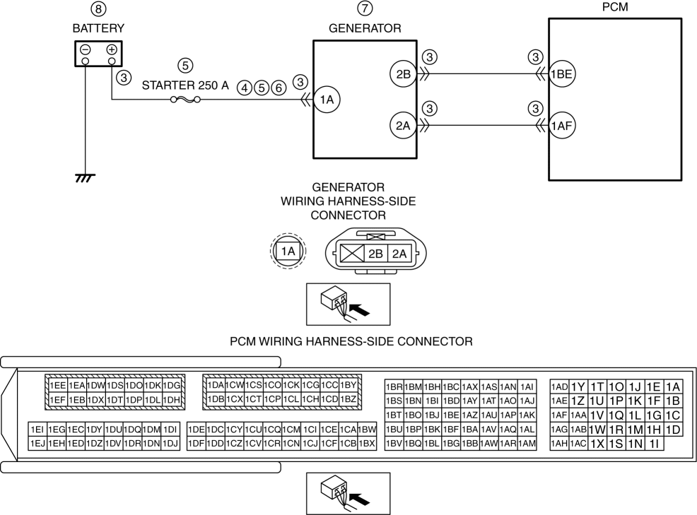
| No | Refer to the wiring diagram and verify whether or not there is a common connector between battery positive terminal and generator terminal 1A.
Go to Step 8. |
||
| 5 | PURPOSE: INSPECT FUSE
| Yes | If the fuse is blown:
If the fuse is damaged:
Go to Step 8. |
| No | Reinstall the STARTER 250 A fuse, then go to the next step. |
||
| 6 | PURPOSE: VERIFY IF OPEN CIRCUIT IN GENERATOR CHARGE/DISCHARGE CIRCUIT AFFECTS DIAGNOSTIC RESULTS
| Yes | Go to the next step. |
| No | Refer to the wiring diagram and verify whether or not there is a common connector between battery positive terminal and generator terminal 1A.
Go to Step 8. |
||
| 7 | PURPOSE: DETERMINE INTEGRITY OF GENERATOR
| Yes | Replace the generator, then go to the next step. (See GENERATOR REMOVAL/INSTALLATION [SKYACTIV-G 2.5 (WITHOUT i-ELOOP)].) |
| No | Go to the next step. |
||
| 8 | PURPOSE: VERIFY CONDITIONS OF BATTERY
| — | Follow the inspection instructions, then go to the next step. |
| 9 | PURPOSE: VERIFICATION OF VEHICLE REPAIR COMPLETION
| Yes | Repeat the inspection from Step 1.
Go to the next step. |
| No | Go to the next step. |
||
| 10 | PURPOSE: VERIFY IF THERE IS ANY OTHER MALFUNCTION
| Yes | Go to the applicable DTC inspection. (See DTC TABLE [SKYACTIV-G 2.5].) |
| No | DTC troubleshooting completed. |
| DESCRIPTION | Generator system: Voltage generated by generator is high |
|
| DETECTION CONDITION | Determination conditions |
|
| Preconditions |
|
|
| Malfunction determination period |
|
|
| Drive cycle |
|
|
| Self test type |
|
|
| Sensor used |
|
|
| FAIL-SAFE FUNCTION |
|
|
| VEHICLE STATUS WHEN DTCs ARE OUTPUT |
|
|
| POSSIBLE CAUSE |
|
|
When the charge/discharge circuit for the power supplying the vehicle is normal, the vehicle will operate normally.
If the PCM detects any of the following conditions, it determines that the generator is over-charging and verification of vehicle malfunctions/safety assurance is performed.
Vehicle capacitor (i-ELOOP) and battery voltage are specified value or more
Large difference between field current value demanded of generator from PCM and field current value returned from generator
Signal from generator notifying of malfunction is received
Clear the DTC from the PCM memory using the M-MDS. (See CLEARING DTC [SKYACTIV-G 2.5].)
Start the engine.
Leave for 30 s while idling with no electrical load.
Leave for 30 s while idling with high electrical load.
Not applicable.
| STEP | INSPECTION | RESULTS | ACTION |
| 1 | PURPOSE: VERIFY RELATED SERVICE INFORMATION AVAILABILITY
| Yes | Perform repair or diagnosis according to the available Service Information.
|
| No | Go to the next step. |
||
| 2 | PURPOSE: VERIFY IF GENERATOR OUTPUT IS AFFECTED BY DTC OCCURRING FROM DC-DC CONVERTER RELATED PART
| Yes | Repair or replace the malfunctioning part according to the applicable DTC troubleshooting. (See DTC TABLE [i-ELOOP].) Go to the next step. |
| No | Go to the next step. |
||
| 3 | PURPOSE: VERIFY DTC
| Yes | Go to the applicable DTC inspection. (See DTC TABLE [SKYACTIV-G 2.5].) Go to the troubleshooting procedure to perform the procedure from Step 1. |
| No | Go to the troubleshooting procedure to perform the procedure from Step 1. |
Intention of troubleshooting procedure
Step 1—4
Perform inspection of each signal transmission system.
Step 5
Inspect the capacitor (i-ELOOP) installation condition.
Step 6
Inspect the area around the generator for abnormalities.
Step 7
Perform a unit inspection of the generator.
Step 8—10
Verify that primary malfunction is resolved and there are no other malfunctions.
| STEP | INSPECTION | RESULTS | ACTION |
| 1 | PURPOSE: VERIFY IF POOR CONNECTION OF EACH PART AFFECTS DIAGNOSTIC RESULTS
| Yes | Go to the next step. |
| No | Connect each part or the connector correctly, then go to the next step. |
||
| 2 | PURPOSE: VERIFY IF CONNECTOR DAMAGE OF EACH PART AFFECTS DIAGNOSTIC RESULTS
| Yes | Repair or replace the connector and/or terminals, then go to the next step. |
| No | Go to the next step. |
||
| 3 | PURPOSE: VERIFY IF SHORT TO POWER SUPPLY IN EACH WIRING HARNESS AFFECTS DIAGNOSTIC RESULTS
| Yes | Go to the next step. |
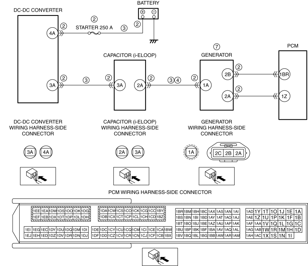
| No | Refer to the wiring diagram and verify whether or not there is a common connector between the following terminals:
Go to the next step. |
||
| 4 | PURPOSE: VERIFY IF OPEN CIRCUIT IN GENERATOR CHARGE/DISCHARGE CIRCUIT AFFECTS DIAGNOSTIC RESULTS
| Yes | Go to the next step. |
| No | Refer to the wiring diagram and verify whether or not there is a common connector between capacitor (i-ELOOP) terminal 2A and generator terminal 1A.
Go to the next step. |
||
| 5 | PURPOSE: INSPECT INSTALLATION OF CAPACITOR (i-ELOOP)
| Yes | Go to the next step. |
| No | Retighten the capacitor (i-ELOOP), then go to the next step. |
||
| 6 | PURPOSE: VERIFY IF THERE IS MALFUNCTION CAUSED BY TEMPERATURE INCREASE AROUND GENERATOR
| Yes | Eliminate the abnormality around the generator, then go to the next step. |
| No | Go to the next step. |
||
| 7 | PURPOSE: DETERMINE INTEGRITY OF GENERATOR
| Yes | Replace the generator, then go to the next step. |
| No | Go to the next step. |
||
| 8 | PURPOSE: VERIFY CONDITIONS OF BATTERY
| — | Follow the inspection instructions, then go to the next step. |
| 9 | PURPOSE: VERIFICATION OF VEHICLE REPAIR COMPLETION
| Yes | Repeat the inspection from Step 1.
Go to the next step. |
| No | Go to the next step. |
||
| 10 | PURPOSE: VERIFY IF THERE IS ANY OTHER MALFUNCTION
| Yes | Go to the applicable DTC inspection. (See DTC TABLE [SKYACTIV-G 2.5].) |
| No | DTC troubleshooting completed. |