NOTE:
To determine the malfunctioning part, proceed with the diagnostics from “Function Inspection Using M-MDS”.
| DESCRIPTION | Generator system: Malfunction in voltage generated by generator |
|
| DETECTION CONDITION | Determination conditions |
|
| Preconditions |
|
|
| Malfunction determination period |
|
|
| Drive cycle |
|
|
| Self test type |
|
|
| Sensor used |
|
|
| FAIL-SAFE FUNCTION |
|
|
| VEHICLE STATUS WHEN DTCs ARE OUTPUT |
|
|
| POSSIBLE CAUSE |
|
|
When the charge/discharge circuit for the power supplying the vehicle is normal, the vehicle will operate normally. In this diagnostic, a low vehicle supply voltage is detected even though the generator is generating power, a malfunction in the charge/discharge circuit is detected, and verification of vehicle malfunctions/safety assurance is performed.
Clear the DTC from the PCM memory using the M-MDS. (See CLEARING DTC [SKYACTIV-G 2.5].)
Start the engine.
Leave for 180 s while idling with no electrical load.
Leave for 30 s while idling with high electrical load.
Not applicable
Intention of troubleshooting procedure
Step 1—6
Perform an inspection of each signal transmission system.
Step 7
Perform a unit inspection of the generator.
Step 8—10
Verify that the primary malfunction is resolved and there are no other malfunctions.
| STEP | INSPECTION | RESULTS | ACTION |
| 1 | PURPOSE: VERIFY RELATED REPAIR INFORMATION AVAILABILITY
| Yes | Perform repair or diagnosis according to the available repair information.
|
| No | Go to the next step. |
||
| 2 | PURPOSE: VERIFY IF POOR CONNECTION OF EACH PART AFFECTS DIAGNOSTIC RESULTS
| Yes | Go to the next step. |
| No | Connect each part or the connector correctly, then go to Step 8. |
||
| 3 | PURPOSE: VERIFY IF CONNECTOR DAMAGE OF EACH PART AFFECTS DIAGNOSTIC RESULTS
| Yes | Repair or replace the connector and/or terminals, then go to Step 8. |
| No | Go to the next step. |
||
| 4 | PURPOSE: INSPECT FUSE
| Yes | If the fuse is blown:
If the fuse is damaged:
Go to Step 8. |
| No | Reinstall the STARTER 250 A fuse, then go to the next step. |
||
| 5 | PURPOSE: VERIFY IF SHORT TO GROUND IN GENERATOR CHARGE/DISCHARGE CIRCUIT AFFECTS DIAGNOSTIC RESULTS
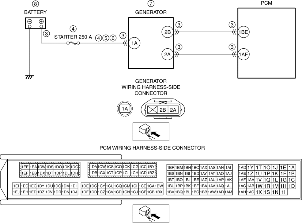
| Yes | Refer to the wiring diagram and verify whether or not there is a common connector between battery positive terminal and generator terminal 1A.
Go to Step 8. |
| No | Go to the next step. |
||
| 6 | PURPOSE: VERIFY IF OPEN CIRCUIT IN GENERATOR CHARGE/DISCHARGE CIRCUIT AFFECTS DIAGNOSTIC RESULTS
| Yes | Go to the next step. |
| No | Refer to the wiring diagram and verify whether or not there is a common connector between battery positive terminal and generator terminal 1A.
Go to Step 8. |
||
| 7 | PURPOSE: DETERMINE INTEGRITY OF GENERATOR
| Yes | Replace the generator, then go to the next step. (See GENERATOR REMOVAL/INSTALLATION [SKYACTIV-G 2.5 (WITHOUT i-ELOOP)].) |
| No | Go to the next step. |
||
| 8 | PURPOSE: VERIFY CONDITIONS OF BATTERY
| — | Follow the inspection instructions, then go to the next step. |
| 9 | PURPOSE: VERIFICATION OF VEHICLE REPAIR COMPLETION
| Yes | Repeat the inspection from Step 1.
Go to the next step. |
| No | Go to the next step. |
||
| 10 | PURPOSE: VERIFY IF THERE IS ANY OTHER MALFUNCTION
| Yes | Go to the applicable DTC inspection. (See DTC TABLE [SKYACTIV-G 2.5].) |
| No | DTC troubleshooting completed. |
| DESCRIPTION | Generator system: Malfunction in voltage generated by generator |
|
| DETECTION CONDITION | Determination conditions |
|
| Preconditions |
|
|
| Malfunction determination period |
|
|
| Drive cycle |
|
|
| Self test type |
|
|
| Sensor used |
|
|
| FAIL-SAFE FUNCTION |
|
|
| VEHICLE STATUS WHEN DTCs ARE OUTPUT |
|
|
| POSSIBLE CAUSE |
|
|
When the charge/discharge circuit for the power supplying the vehicle is normal, the vehicle will operate normally. In this diagnostic, a low vehicle supply voltage is detected even though the generator is generating power, a malfunction in the charge/discharge circuit is detected, and verification of vehicle malfunctions/safety assurance is performed.
Clear the DTC from the PCM memory using the M-MDS. (See CLEARING DTC [SKYACTIV-G 2.5].)
Start the engine.
Leave for 180 s while idling with no electrical load.
Leave for 30 s while idling with high electrical load.
Not applicable.
| STEP | INSPECTION | RESULTS | ACTION |
| 1 | PURPOSE: VERIFY RELATED REPAIR INFORMATION AVAILABILITY
| Yes | Perform repair or diagnosis according to the available repair information.
|
| No | Go to the next step. |
||
| 2 | PURPOSE: VERIFY IF PRE-CHARGE WARNING IS DISPLAYED OR NOT
| Yes | Go to the next step. |
| No | Go to the troubleshooting procedure to perform the procedure from Step 1. |
||
| 3 | PURPOSE: VERIFY IF GENERATOR OUTPUT IS AFFECTED BY DTC OCCURRING FROM DC-DC CONVERTER RELATED PART
NOTE:
| Yes | Repair or replace the malfunctioning part according to the applicable DTC troubleshooting. (See DTC TABLE [i-ELOOP].) Go to the next step. |
| No | Go to the next step. |
||
| 4 | PURPOSE: VERIFY DTC
| Yes | Go to the applicable DTC inspection. (See DTC TABLE [SKYACTIV-G 2.5].) Go to the troubleshooting procedure to perform the procedure from Step 1. |
| No | Go to the troubleshooting procedure to perform the procedure from Step 1. |
Intention of troubleshooting procedure
Step 1
Perform inspection of generator voltage.
Step 2—6
Perform inspection of each signal transmission system.
Step 7
Perform a unit inspection of the generator.
Step 8—10
Verify that primary malfunction is resolved and there are no other malfunctions.
| STEP | INSPECTION | RESULTS | ACTION |
| 1 | PURPOSE: DETERMINE THE MALFUNCTION CAUSE BY VERIFYING THE OUTPUT VOLTAGE OF GENERATOR TERMINAL 1A.
| Yes | Perform the troubleshooting procedure for DTC P2503:00. (See DTC P2503:00 [SKYACTIV-G 2.5].) Go to the next step. |
| No | Go to the next step. |
||
| 2 | PURPOSE: VERIFY IF POOR CONNECTION OF EACH PART AFFECTS DIAGNOSTIC RESULTS
| Yes | Go to the next step. |
| No | Connect each part or the connector correctly, then go to the next step. |
||
| 3 | PURPOSE: VERIFY IF CONNECTOR DAMAGE OF EACH PART AFFECTS DIAGNOSTIC RESULTS
| Yes | Repair or replace the connector and/or terminals, then go to the next step. |
| No | Go to the next step. |
||
| 4 | PURPOSE: INSPECT FUSE
| Yes | If the fuse is blown:
If the fuse is damaged:
Go to the next step. |
| No | Reinstall the STARTER 250 A fuse, then go to the next step. |
||
| 5 | PURPOSE: VERIFY IF SHORT TO GROUND IN EACH WIRING HARNESS AFFECTS DIAGNOSTIC RESULTS
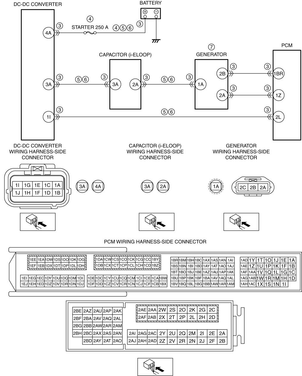
| Yes | Refer to the wiring diagram and verify whether or not there is a common connector between the following terminals:
Go to the next step. |
| No | Go to the next step. |
||
| 6 | PURPOSE: VERIFY IF OPEN CIRCUIT IN EACH WIRING HARNESS AFFECTS DIAGNOSTIC RESULTS
| Yes | Go to the next step. |
| No | Refer to the wiring diagram and verify whether or not there is a common connector between the following terminals:
Go to the next step. |
||
| 7 | PURPOSE: DETERMINE INTEGRITY OF GENERATOR
| Yes | Replace the generator, then go to the next step. |
| No | Go to the next step. |
||
| 8 | PURPOSE: VERIFY CONDITIONS OF BATTERY
| — | Follow the inspection instructions, then go to the next step. |
| 9 | PURPOSE: VERIFICATION OF VEHICLE REPAIR COMPLETION
| Yes | Repeat the inspection from Step 1.
Go to the next step. |
| No | Go to the next step. |
||
| 10 | PURPOSE: VERIFY IF THERE IS ANY OTHER MALFUNCTION
| Yes | Go to the applicable DTC inspection. (See DTC TABLE [SKYACTIV-G 2.5].) |
| No | DTC troubleshooting completed. |