NOTE:
To determine the malfunctioning part, proceed with the diagnostics from "Function Inspection Using M-MDS".
| DESCRIPTION | HO2S circuit low input |
|
| DETECTION CONDITION | Determination conditions |
|
| Preconditions |
|
|
| Malfunction determination period |
|
|
| Drive cycle |
|
|
| Self test type |
|
|
| Sensor used |
|
|
| FAIL-SAFE FUNCTION |
|
|
| VEHICLE STATUS WHEN DTCs ARE OUTPUT |
|
|
| POSSIBLE CAUSE |
|
|
The PCM detects the oxygen concentration in the exhaust gas based on the HO2S signal. The PCM determines a HO2S signal error based on the condition in which the HO2S input voltage continues to be less than the specified value, and stores a DTC.
Warm up the engine to allow the engine coolant temperature to reach 80 °C {176 °F} or more.
Start the engine and leave it idling for 1 min.
NOTE:
Match the engine coolant temperature in the recorded FREEZE FRAME DATA (Mode 2)/snapshot data, the vehicle speed, and engine speed values to the best extent possible while driving the vehicle.
Try to reproduce the malfunction by driving the vehicle for 5 min based on the values in the FREEZE FRAME DATA (Mode 2)/snapshot data.
Not applicable
| STEP | INSPECTION | RESULTS | ACTION |
| 1 | PURPOSE: VERIFY RELATED REPAIR INFORMATION AVAILABILITY
| Yes | Perform repair or diagnosis according to the available repair information.
|
| No | Go to the next step. |
||
| 2 | PURPOSE: RECORD VEHICLE STATUS AT TIME OF DTC DETECTION TO UTILIZE WITH REPEATABILITY VERIFICATION
| Yes | Go to the troubleshooting procedure to perform the procedure from Step 1. |
| No | Record the FREEZE FRAME DATA (Mode 2)/snapshot data on the repair order. NOTE:
Go to the troubleshooting procedure to perform the procedure from Step 1. |
Intention of troubleshooting procedure
Step 1—4
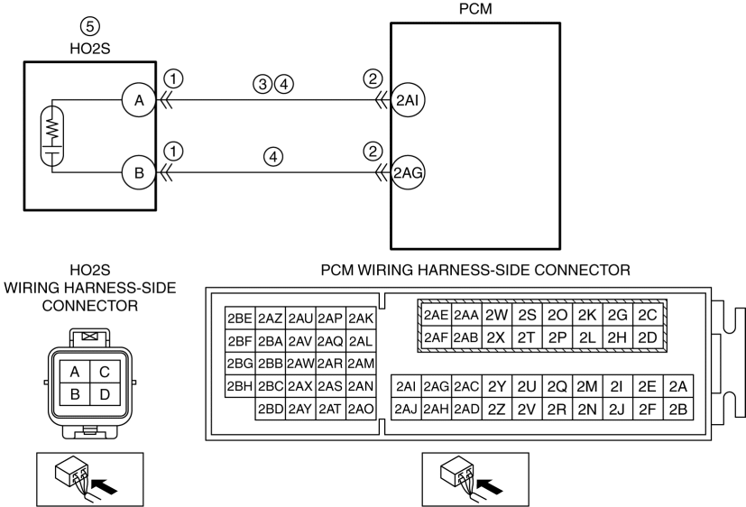
Perform an inspection of the HO2S and PCM-related connectors and wiring harnesses.
Step 5
Perform a unit inspection of the HO2S.
Step 6—7
Verify that the primary malfunction is resolved and there are no other malfunctions.
| STEP | INSPECTION | RESULTS | ACTION |
| 1 | PURPOSE: INSPECT HO2S CONNECTOR CONDITION
| Yes | Repair or replace the connector and/or terminals, then go to Step 6. |
| No | Go to the next step. |
||
| 2 | PURPOSE: INSPECT PCM CONNECTOR CONDITION
| Yes | Repair or replace the connector and/or terminals, then go to Step 6. |
| No | Go to the next step. |
||
| 3 | PURPOSE: INSPECT HO2S SIGNAL CIRCUIT FOR SHORT TO GROUND
| Yes | Refer to the wiring diagram and verify whether or not there is a common connector between HO2S terminal A and PCM terminal 2AI.
Go to Step 6. |
| No | Go to the next step. |
||
| 4 | PURPOSE: INSPECT HO2S CIRCUIT FOR OPEN CIRCUIT
| Yes | Go to the next step. |
| No | Refer to the wiring diagram and verify whether or not there is a common connector between the following terminals:
Go to Step 6. |
||
| 5 | PURPOSE: DETERMINE INTEGRITY OF HO2S
| Yes | Replace the HO2S, then go to the next step. (See HEATED OXYGEN SENSOR (HO2S) REMOVAL/INSTALLATION [SKYACTIV-G 2.5].) |
| No | Go to the next step. |
||
| 6 | PURPOSE: VERIFICATION OF VEHICLE REPAIR COMPLETION
| Yes | Repeat the inspection from Step 1.
Go to the next step. |
| No | Go to the next step. |
||
| 7 | PURPOSE: VERIFY IF THERE IS ANY OTHER MALFUNCTION
| Yes | Go to the applicable DTC inspection. (See DTC TABLE [SKYACTIV-G 2.5].) |
| No | DTC troubleshooting completed. |