1. Disconnect the negative battery cable. (See NEGATIVE BATTERY CABLE DISCONNECTION/CONNECTION [SKYACTIV-G 2.5].)
2. Remove the rear combination light. (See REAR COMBINATION LIGHT REMOVAL/INSTALLATION.)
3. Remove the rear bumper. (See REAR BUMPER REMOVAL/INSTALLATION.)
4. Connect the negative battery cable. (See NEGATIVE BATTERY CABLE DISCONNECTION/CONNECTION [SKYACTIV-G 2.5].)
5. Verify that the voltages of each of the terminals are as indicated in the terminal voltage table (reference).
If the voltage is not as specified in the terminal voltage table (reference), inspect the parts under Inspection item(s).
If the system does not operate normally even though the inspection items are normal, replace the BSM control module (RH) or BSM control module (LH).
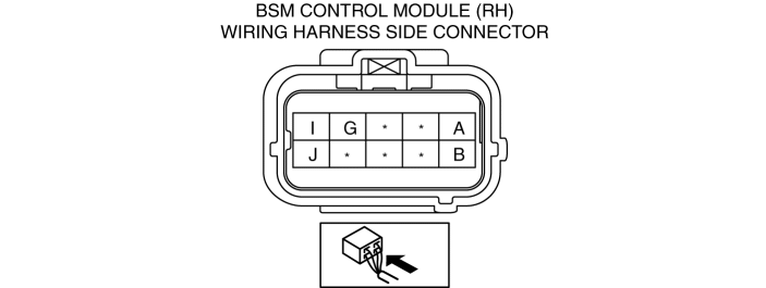
| Terminal | Signal name | Connected to | Measurement conditions | Voltage (V) | Inspection item(s) |
|
| A | CAN2_H | BSM control module (RH) | Because this terminal is for communication, determination using terminal voltage inspection is not possible. |
|||
| B | CAN2_L | BSM control module (RH) | Because this terminal is for communication, determination using terminal voltage inspection is not possible. |
|||
| C | MS-CAN_H | Related module | Because this terminal is for communication, determination using terminal voltage inspection is not possible. |
|||
| D | MS-CAN_L | Related module | Because this terminal is for communication, determination using terminal voltage inspection is not possible. |
|||
| E | — | — | — | — | — |
|
| F | — | — | — | — | — |
|
| G | BSM indicator light (LH) signal | BSM indicator light (LH) | Turn off BSM indicator light using BSM system active command WRN_IND_L | 0.8 or less |
|
|
| Turn on BSM indicator light using rear BSM system active command WRN_IND_L | B+ |
|||||
| H | — | — | — | — | — |
|
| I | Power position (IG1) | IG relay | Ignition switched ON (engine off or on) | B+ |
|
|
| Ignition switched off (LOCK) or ACC | 1.0 or less |
|||||
| J | Ground | Body ground | Under any condition | 1.0 or less |
|
|
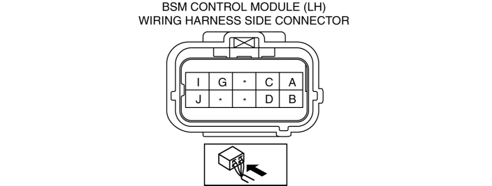
| Terminal | Signal name | Connected to | Measurement conditions | Voltage (V) | Inspection item(s) |
|
| A | CAN2_H | BSM control module (LH) | Because this terminal is for communication, determination using terminal voltage inspection is not possible. |
|||
| B | CAN2_L | BSM control module (LH) | Because this terminal is for communication, determination using terminal voltage inspection is not possible. |
|||
| C | — | — | — | — | — |
|
| D | — | — | — | — | — |
|
| E | — | — | — | — | — |
|
| F | — | — | — | — | — |
|
| G | BSM indicator light (RH) signal | BSM indicator light (RH) | Turn off BSM indicator light using BSM system active command WRN_IND_R | 0.8 or less |
|
|
| Turn on BSM indicator light using rear BSM system active command WRN_IND_R | B+ |
|||||
| H | — | — | — | — | — |
|
| I | Power position (IG1) | IG relay | Ignition switched ON (engine off or on) | B+ |
|
|
| Ignition switched off (LOCK) or ACC | 1.0 or less |
|||||
| J | Ground | Body ground | Under any condition | 1.0 or less |
|
|