|
|
| Step | Inspection | Action |
| 1 | INSPECT BATTERY VOLTAGE
| Yes | Make sure that battery terminal connection is okay. Go to the next step. |
| No | Charge or replace the battery, then go to Step 6. (See BATTERY RECHARGING [SKYACTIV-G 2.5].) (See BATTERY REMOVAL/INSTALLATION [SKYACTIV-G 2.5].) |
| 2 | INSPECT BATTERY GRAVITY
| Yes | Go to the next step. |
| No | Replace the battery, then go to Step 6. (See BATTERY REMOVAL/INSTALLATION [SKYACTIV-G 2.5].) |
| 3 | INSPECT CHARGING SYSTEM
| Yes | Go to the next step. |
| No | Replace the generator and/or drive belt if necessary. Go to step 6. (See GENERATOR REMOVAL/INSTALLATION [SKYACTIV-G 2.5 (WITHOUT i-ELOOP)].) (See GENERATOR REMOVAL/INSTALLATION [i-ELOOP].) (See DRIVE BELT REMOVAL/INSTALLATION [SKYACTIV-G 2.5].) |
| 4 | INSPECT FUSE CONDITION
| Yes | Go to the next step. |
| No | Replace the fuse, then go to Step 7. |
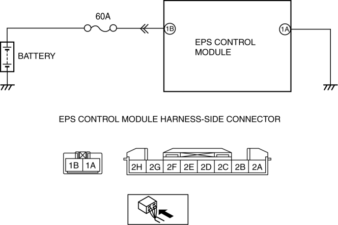
| 5 | INSPECT EPS CM POWER SUPPLY CIRCUIT FOR OPEN OR SHORT CIRCUIT
| Yes | Go to the next Step. |
| No | Repair or replace the wiring harness (including fuse) between the EPS CM and ground, then go to Step 6. |
| 6 | INSPECT EPS CM GROUND CIRCUIT FOR POOR GROUND OR OPEN CIRCUIT
| Yes | Go to the next step. |
| No | Repair or replace the wiring harness between terminal 1A and body ground, then go to the next step. |
| 7 | VERIFY THAT THE SAME DTC IS NOT PRESENT
| Yes | Replace the steering column, then go to the next step. (See STEERING WHEEL AND COLUMN REMOVAL/INSTALLATION.) |
| No | Go to the next step. |
| 8 | VERIFY THAT NO OTHER DTCs ARE PRESENT
| Yes | Go to the applicable DTC inspection. (See ELECTRIC POWER STEERING (EPS) ON-BOARD DIAGNOSIS.) |
| No | DTC troubleshooting completed. |
