1. Switch the ignition ON (engine off).
2. Shift the selector lever to the P position.
3. Verify that the selector lever cannot be shifted from P to R position when the brake pedal is released.
If it can be verified, go to the next step.
If not as verified, inspect the following parts:
Shift-lock solenoid (See Shift-Lock Solenoid Inspection.)
Not P position switch (See NOT P POSITION SWITCH INSPECTION.)
Brake switch (See BRAKE PEDAL INSPECTION.)
Start stop unit (See START STOP UNIT INSPECTION.)
PCM (See PCM INSPECTION [SKYACTIV-G 2.5].)
4. Verify that the selector lever can be shifted from P to R position when the brake pedal is depressed.
If it can be verified, go to the next step.
If not as verified, inspect the following parts:
Shift-lock solenoid (See Shift-Lock Solenoid Inspection.)
Not P position switch (See NOT P POSITION SWITCH INSPECTION.)
Brake switch (See BRAKE PEDAL INSPECTION.)
Start stop unit (See START STOP UNIT INSPECTION.)
PCM (See PCM INSPECTION [SKYACTIV-G 2.5].)
NOTE:
The shift-lock solenoid is built into the selector lever component.
NOTE:
There are two types of automatic transaxle shift mechanisms.
Type A: Gate-shaped key type. There is no lock release button on the selector lever knob.
Type B: Gate-shaped straight type. There is a lock release button on the selector lever knob.
1. Disconnect the negative battery cable. (See NEGATIVE BATTERY CABLE DISCONNECTION/CONNECTION [SKYACTIV-G 2.5].)
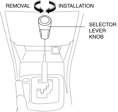
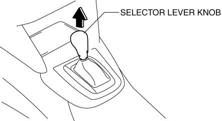
2. Remove the selector lever knob (type A).
3. Perform the following procedure to remove the selector lever knob (type B).NOTE:
If the servicing is difficult, release the shift lock manually and shift the selector lever to the N position.
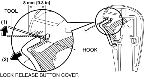
a. Insert the tool (width: 6 mm or less, thickness: 1 mm or less) as shown in the figure.
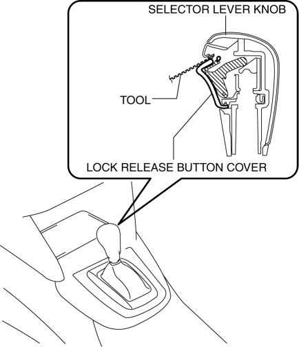 b. Move the tool in the direction of arrow (1) in the figure and detach the hook. Move the lock release button cover in the direction of arrow (2) in the figure and remove it.
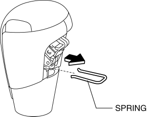
 c. Remove the spring.
 d. Remove the selector lever knob.
4. Remove the front console. (See FRONT CONSOLE REMOVAL/INSTALLATION.)
5. Reconnect the negative battery cable. (See NEGATIVE BATTERY CABLE DISCONNECTION/CONNECTION [SKYACTIV-G 2.5].)
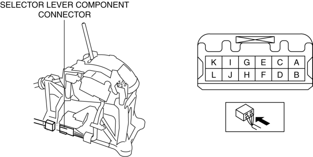
6. Verify that the voltages of each of the selector lever component terminals are as indicated in the table.Type A
Type B
Shift-lock solenoid specification
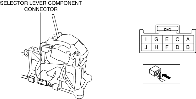
Terminal
Connected to
Test condition
Voltage (V)
A
IG1 relay
Ignition switched ON (engine on)
B+
Except above
Below 1.0
H
Start stop unit
Under any condition
Below 1.0
If the voltage is not as indicated in the table, repair or replace the related wiring harness.
If the voltage can be verified as indicated in the table, replace the selector lever component. (See AUTOMATIC TRANSAXLE SHIFT MECHANISM REMOVAL/INSTALLATION.)
1. Switch the ignition to off.
2. Verify that the selector lever is in the P position.
3. Without the brake pedal depressed, verify that the selector lever cannot be shifted from the P position.
4. Remove the emergency override hole cover using a tape-wrapped flathead screwdriver.
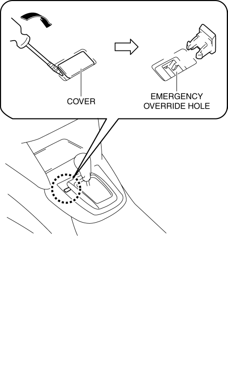
5. Insert the flathead screwdriver into the emergency override hole and push it down.
6. Verify that the selector lever can be shifted from the P position.
If not as verified, replace the selector lever. (See AUTOMATIC TRANSAXLE SHIFT MECHANISM REMOVAL/INSTALLATION.)