If not within the specification, replace the throttle body. (See INTAKE-AIR SYSTEM REMOVAL/INSTALLATION [SKYACTIV-G 2.5].)
Specification
CAUTION:
The inspection cannot be performed with this method correctly if there is a malfunction of the APP sensor or throttle valve actuator. Verify that no DTCs related to the APP sensor or throttle valve actuator are stored before the inspection.
NOTE:
The TP sensor cannot be removed as a single unit. When replacing the TP sensor, replace it together with the throttle body as a single unit.
1. Connect the M-MDS to the DLC–2.
2. Switch the ignition ON (engine off).
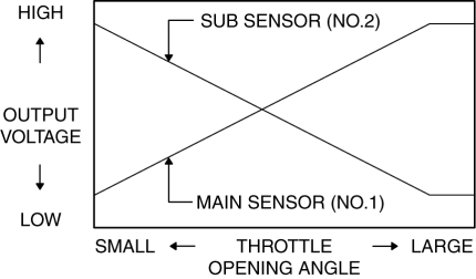
3. Verify that the TP sensor output voltage (PID: TP1, TP2) varies according to the accelerator opening angle when the accelerator opening angle is gradually increased. (See ON-BOARD DIAGNOSTIC TEST [SKYACTIV-G 2.5].)
If verified, go to the next step.
If it cannot be verified, replace the throttle body. (See INTAKE-AIR SYSTEM REMOVAL/INSTALLATION [SKYACTIV-G 2.5].)
4. Verify that the TP sensor output voltage (PID: TP1, TP2) is within the specification when the accelerator pedal is depressed and not depressed. (See ON-BOARD DIAGNOSTIC TEST [SKYACTIV-G 2.5].) (See PCM INSPECTION [SKYACTIV-G 2.5].)
If not within the specification, replace the throttle body. (See INTAKE-AIR SYSTEM REMOVAL/INSTALLATION [SKYACTIV-G 2.5].)
Specification