WARNING:
A hot engine and intake air system can cause severe burns. Turn off the engine and wait until they are cool before removing the intake air system.
1. Disconnect the negative battery cable. (See NEGATIVE BATTERY CABLE DISCONNECTION/CONNECTION [SKYACTIV-G 2.5].)
2. Remove in the order indicated in the table.
3. Install in the reverse order of removal.
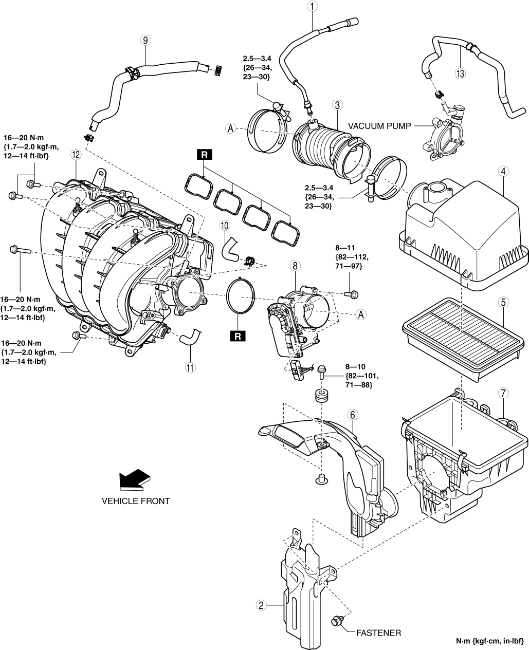
| 1 | Ventilation hose |
| 2 | Resonance chamber |
| 3 | Air hose |
| 4 | Air cleaner cover |
| 5 | Air cleaner element |
| 6 | Fresh-air duct (See Fresh-air Duct Removal Note.) |
| 7 | Air cleaner case |
| 8 | Throttle body |
| 9 | Vacuum hose (between intake manifold and vacuum pump) (See Vacuum Hose Removal Note.) |
| 10 | Evaporative hose |
| 11 | PCV hose |
| 12 | Intake manifold |
| 13 | Vacuum hose (between vacuum pump and power brake unit) |
1. Remove the MAF sensor/IAT sensor No.1. (See MASS AIR FLOW (MAF) SENSOR/INTAKE AIR TEMPERATURE (IAT) SENSOR NO.1 REMOVAL/INSTALLATION [SKYACTIV-G 2.5].)
2. Remove the following parts as a single unit:
Air hose
Air cleaner cover
Air cleaner element
Air cleaner case
Fresh-air duct
Resonance chamber
3. Remove the resonance chamber.
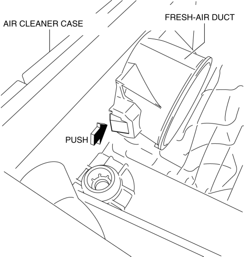
1. Pull out the fresh-air duct while pressing the tab shown in the figure.
1. Remove the plug hole plate. (See PLUG HOLE PLATE REMOVAL/INSTALLATION [SKYACTIV-G 2.5].)
2. Remove the vacuum hose.
1. Remove the MAP sensor/IAT sensor No.2. (See MANIFOLD ABSOLUTE PRESSURE (MAP) SENSOR/INTAKE AIR TEMPERATURE (IAT) SENSOR NO.2 REMOVAL/INSTALLATION [SKYACTIV-G 2.5].)
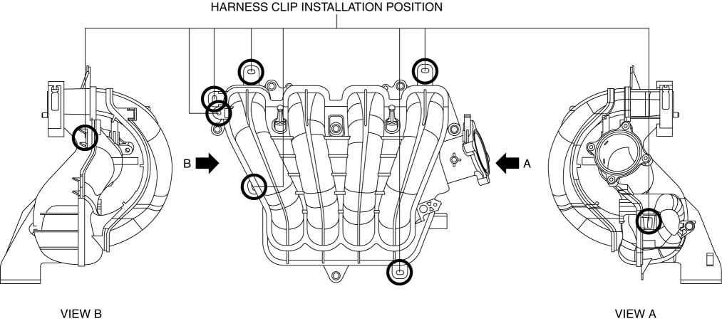
2. Disconnect the harness clip from the intake manifold as shown in the figure.
3. Remove the intake manifold.
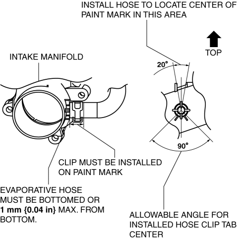
1. Install the evaporative hose as shown in the figure.
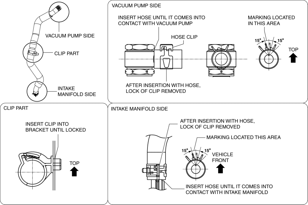
1. Install the vacuum hose as shown in the figure.
1. Install the air cleaner case as shown in the figure.

1. Install the fresh-air duct as shown in the figure.

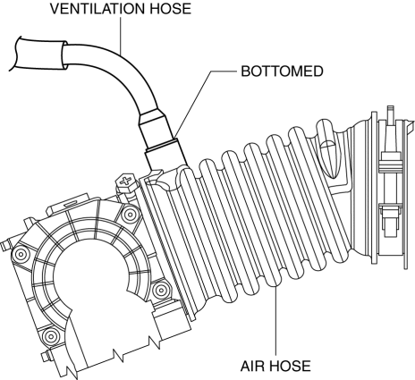
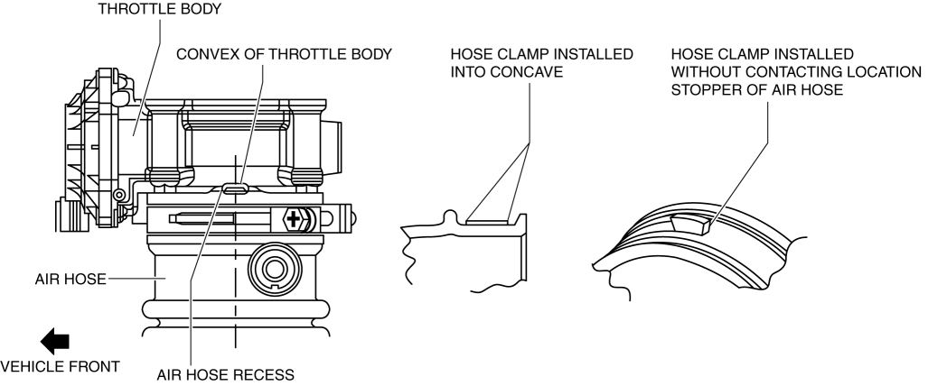
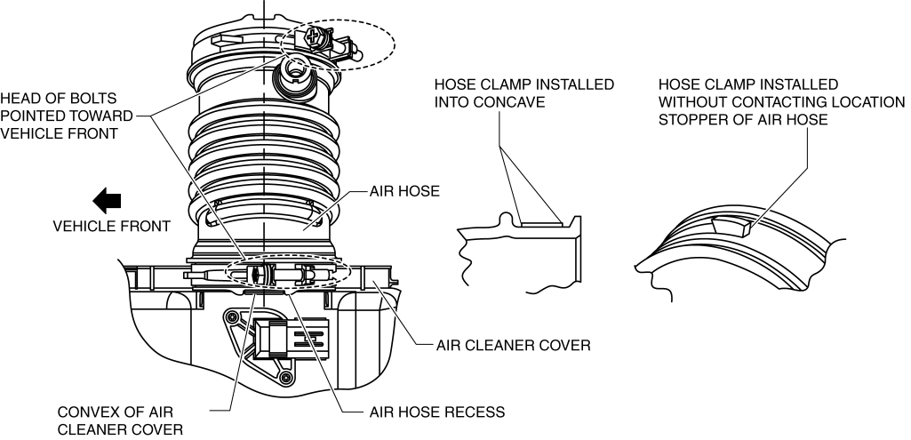
1. Install the air hose as shown in the figure.Throttle body side
Air cleaner side
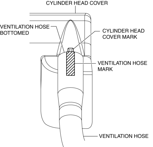
1. Install the ventilation hose as shown in the figure.Cylinder head cover side
Air hose side