< Previous   Next >

2014 - Mazda6 - Brakes

DTC U3003:16/U3003:17/U3003:1C [DYNAMIC STABILITY CONTROL (DSC)]


DTC

U3003:16/U3003:17/U3003:1C

Power supply system

DETECTION CONDITION

  • U3003:16

    • The vehicle speed exceeds 3 km/h {2 mph} and the voltage at DSC HU/CM terminal AG is less than 10 V.

  • U3003:17

    • The voltage at DSC HU/CM terminal AG is 16 V or more.

  • U3003:1C

    • Low ignition voltage (10 V or less) is detected at the voltage monitor of the solenoid valve or motor monitor.

    • The ABS wheel speed sensor power supply for all four wheels decreases for a continuous 60 s with the voltage at DSC HU/CM terminal AG is 10 V or less.

FAIL-SAFE FUNCTION

  • Illuminates the ABS warning light, brake system warning light, TCS/DSC indicator light, and master warning light*.

  • Tire pressure monitoring system warning light illuminates after flashes.

  • Inhibits all of controls.

*: Vehicles with Smart City Brake Support (SCBS).

POSSIBLE CAUSE

  • Malfunction of fuse (ABS/DSC M 50A or ABS/DSC S 30A)

  • Open or short circuit in wiring harness between DSC HU/CM terminal AG and battery

  • Open circuit in wiring harness between DSC HU/CM terminal A and body ground

  • Battery deterioration

  • Generator malfunction

  • Poor connection at connectors (female terminal)
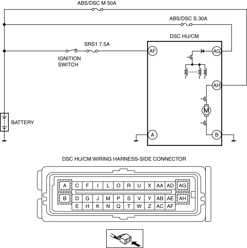

Diagnostic procedure

STEP

INSPECTION

ACTION

1

INSPECT BATTERY VOLTAGE
  • Is the battery positive terminal voltage normal?

Yes

Inspect for normal connection of the battery terminals.

Go to the next step.

No

Charge or replace the battery, then go to Step 7.

(See BATTERY RECHARGING [SKYACTIV-G 2.5].)

(See BATTERY REMOVAL/INSTALLATION [SKYACTIV-G 2.5].)

2

INSPECT BATTERY GRAVITY
  • Is battery specific gravity as specified?

Yes

Go to the next step.

No

Replace the battery, then go to Step 7.

(See BATTERY REMOVAL/INSTALLATION [SKYACTIV-G 2.5].)

3

INSPECT CHARGING SYSTEM
  • Are the generator and the drive belt tensions normal?

Yes

Go to the next step.

No

Replace the generator and/or drive belt if necessary.

(See GENERATOR REMOVAL/INSTALLATION [SKYACTIV-G 2.5 (WITHOUT i-ELOOP)].)

(See GENERATOR REMOVAL/INSTALLATION [i-ELOOP].)

(See DRIVE BELT REMOVAL/INSTALLATION [SKYACTIV-G 2.5].)

Go to Step 7.

4

INSPECT DSC FUSE CONDITION
  • Is the DSC fuse (MAIN 125A, ABS/DSC M 50A and ABS/DSC S 30A) normal?

Yes

Go to the next step.

No

Replace the fuse, then go to Step 7.

5

INSPECT DSC HU/CM POWER SUPPLY FOR OPEN CIRCUIT
  • Disconnect the DSC HU/CM connector.

  • Switch the ignition ON.

  • Measure the voltage between following connector terminals of the DSC HU/CM (vehicle harness-side) and body ground:

    • DSC HU/CM: AG—Body ground

  • Is the voltage 10 V or more?

Yes

Go to the next step.

No

Repair or replace the wiring harness, then go to Step 7.

6

INSPECT DSC HU/CM GROUND FOR POOR GROUND OR OPEN CIRCUIT
  • Switch the ignition off.

  • Measure the resistance between the following connector terminal of DSC HU/CM (vehicle harness-side) and body ground:

    • DSC HU/CM: A—Body ground

  • Is the resistance within 0—1 ohm?

Yes

Go to the next step.

No

If there is open circuit:

  • Repair or replace the wiring harness, then go to the next step.

If resistance is not within specification:

  • Repair or replace the poor ground part, then go to the next step.

7

VERIFY THAT SAME DTC IS NOT PRESENT

Yes

Repeat the inspection from Step 1.

If the malfunction recurs, replace the DSC HU/CM, then go to the next step.

(See DSC HU/CM REMOVAL/INSTALLATION)

No

Go to the next step.

8

VERIFY THAT NO OTHER DTCS ARE PRESENT
  • Are any other DTCs output?

Yes

Go to the applicable DTC inspection.

(See ON-BOARD DIAGNOSIS [DYNAMIC STABILITY CONTROL (DSC)].)

No

DTC troubleshooting completed.


< Previous   Next >
Back to Top
© 2012 Mazda North American Operations, U.S.A.