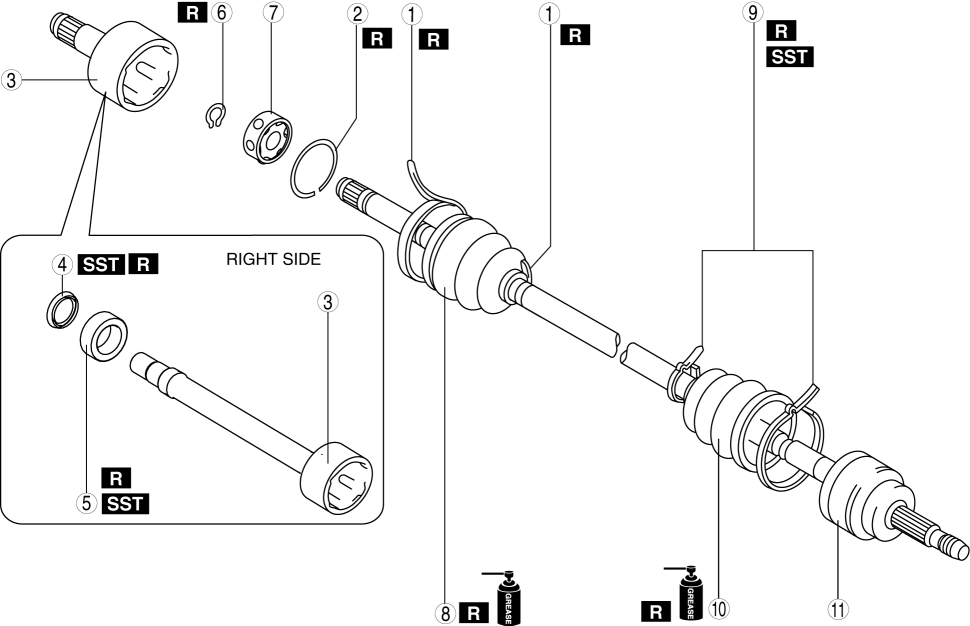
1. Disassemble in the order indicated in the table.
2. Assemble in the reverse order of disassembly.
| 1 | Boot band |
| 2 | Clip (See Clip Disassembly Note.) |
| 3 | Outer ring (See Outer Ring Assembly Note.) |
| 4 | Dust cover (if equipped) (See FRONT DRIVE SHAFT (TRIPOD JOINT) DISASSEMBLY/ASSEMBLY.) |
| 5 | Bearing (See FRONT DRIVE SHAFT (TRIPOD JOINT) DISASSEMBLY/ASSEMBLY.) |
| 6 | Snap ring (See Snap Ring Disassembly Note.) |
| 7 | Balls, inner ring, cage |
| 8 | Boot (See Boot Assembly Note.) |
| 9 | Boot band |
| 10 | Boot (See Boot Assembly Note.) |
| 11 | Shaft and ball joint component |
NOTE:
Remove the boot band only if there is a malfunction.
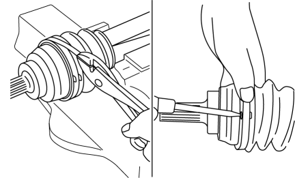
1. Pry up the locking clips using a screwdriver.
2. Pull back the end of the band.
CAUTION:
Mark with paint; do not use a punch.
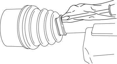
1. Mark the drive shaft and outer ring for proper assembly.
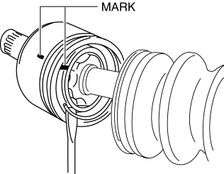
CAUTION:
Mark with paint; do not use a punch.
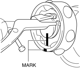
1. Mark the drive shaft end and inner ring for proper assembly.
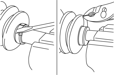
NOTE:
Remove the boot band only if there is a malfunction.
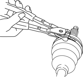
1. Remove the boot band using end clamp pliers.
NOTE:
The wheel-side and transaxle-side boots are different.
1. Fill the boot (wheel side) with the specified grease.NOTE:
Do not touch grease with your hand. Apply it from the tube to prevent foreign matter from entering the boot.
Grease amount
95—115 g {3.4—4.0 oz}
2. Install the boot with the splines of the shaft still wrapped in tape from disassembly.
3. Remove the tape.
1. Adjust clearance A by turning the adjusting bolt of the SST.
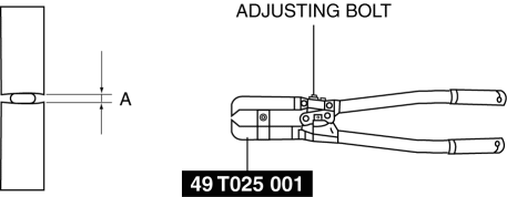
Clearance A
Large diameter side: 3.2 mm {0.13 in}
Small diameter side: 2.9 mm {0.11 in}
2. Crimp the wheel side boot band using the SST. Verify that clearance B is within the specification.Large diameter side
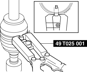
Small diameter side
Clearance B
1.2—4.0 mm {0.05—0.15 in}
If clearance B is more than the specification, reduce clearance A of the SST and crimp the boot band again.
If clearance B is less than the specification, replace the boot band, increase clearance A of the SST, and crimp the new boot band.
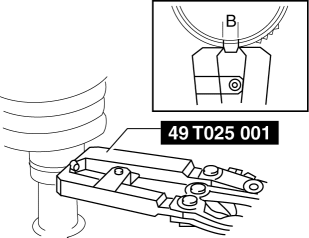
3. Verify that the boot band does not protrude from the boot band installation area
If it does, replace the boot band and repeat Steps 1 and 2.
1. Align the marks and install the balls and cage to the inner ring in the direction shown in the figure.CAUTION:
Install the cage so that the major diameter is at the same side as the snap ring groove. If incorrectly installed, the drive shaft may become disengaged.
2. Align the marks and install the inner ring to the shaft.
3. Install a new snap ring.
1. Fill the outer ring and boot (transaxle side) with the specified grease.NOTE:
Do not touch grease with your hand. Apply it from the tube to prevent foreign matter from entering the boot.
Grease amount
85—105 g {3.0—3.7 oz}
2. Install the outer ring on to the shaft.
3. Install the boot.
4. Set the drive shaft to the standard length.Front drive shaft standard length (MTX)
LH
673.4—683.4 mm {26.52—26.90 in}
RH
1036.7—1046.7 mm {40.815—41.208 in}
5. Release any trapped air from the boots by carefully lifting up the small end of each boot with a cloth wrapped screwdriver.
CAUTION:
Be careful not to allow the grease to leak.
Do not damage the boot.
6. Verify that the drive shaft length is within the specification.
1. Fold the band in the direction opposite to the forward revolving direction of the drive shaft and use pliers to pull it tight.
CAUTION:
Verify that the boot band is installed into the groove securely.